You are currently viewing only those items made visible to the public. Click here to sign in and view the full catalogue.

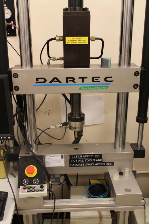
Dartec HC10 Fatigue Tester
| MANUFACTURER | Dartec |
|---|---|
| MODEL | HC10 |
| CONTACT 1 | Jonathan Knowles |
|---|---|
| Enquire about this item | |
| SITE | Eastman Dental Institute |
Description
The Dartec HC10 consists of a test frame fitted with a movable crosshead. The crosshead can be adjusted to a suitable height in order to accommodate a specifictest design. The user is able to set up the limits and parameters of their test using the cyclic generator application under the toolkit 96 software. Upper and lower limits need tobe set in either in load or stroke mode in order to carry out a cyclic test. In reality these limits would be the definitive parameters of the test, however, as the machine is subject to some given error the user can define error bands or a region of error around these limits in which the actuator is constrained to. Safety features are available in the software that can be set which allows the machine to act automatically. Such actions can involve shutting down the hydraulicpressure or subjecting the machine to operate in set up mode (idle mode) once a particular safety limit has been exceeded. The Toolkit 96 software has a number of data collection and analysis applications. The data acquisition tool can be set to collect data over a very short period of time i.e. over 10 or 20 seconds. It can also be set up to automatically collect a very short range of data at a given cycle number. Alternatively the user can set the software to collect data by continuous logging data points for the duration of the test.
Specification
The Dartec HC10 consists of a test frame fitted with a movable crosshead. The crosshead can be adjusted to a suitable height in order to accommodate a specifictest design. The piston head is fitted with an attachment that enables the user to interchange between load cells (100N, 1kN and 10kN). To enable the application of cyclic loads or static loads the machine is equipped with a Dartec 9610 control unit which interfaces between the software and theactuator (piston-load cell). The test frame is engineered as such that the force applied by the load cell during a test is driven by hydraulic pressure supplied by a hydraulic unit. A servo valve fitted on to the crosshead provides a close loop flow or pressure response as a result of programmed values in the control loop application available in the software. This enables the machine to control the output pressure whilst testing. There is a large bolt fitting at the bottom of the test frame which runs along the axis of the actuator. A number of test designs can be manufactured and adapted to be bolted onto the bottom of the test frame. These can include models that are specifically designed to characterise the insertion and removal force of O rings ondental implants over a given number of cycles. There is also an environment chamber available which has been manufactured to be bolted directly onto the test frame and to also accommodate testing jigs. Theenvironment chamber can be attached to a unit comprising of a pump and a temperature controller that can apply a dynamic flow of water at regulated temperature around the environment chamber. This enables the user to characterise the behaviour of materials under wet dynamic conditions in much the same way as implant materials do under physiological conditions.
Item ID #.
Last Updated: 16th July, 2014
There are no publically available categories listed at present. You may have to sign in to browse this catalogue.
